Fleisch Pneumotachograph
***TEMPORARILY UNAVAILABLE***
| The principle of the Pneumotachograph rests on Poiseuille’s Law, which states that, under capillary conditions, in a straight rigid tube, delivery is proportional to pressure loss per unit of length. The continuous measurement of the pressure loss, that is the measurement of the pressure difference between two points on the tube, gives a differential curve whose ordinates represent the velocity of the air current.
To avoid turbulence the air passes through a large number of ducts of 0.8 mm. diameter and 32 mm. in length. The outer ducts (2) are used to measure the pressure. The brass tube (3) has two rows of small holes (4) distributed over its entire circumference and communicating with the annular ducts (5) and (5a). The pressure is then transmitted through the tubes (6) and (6a) to the differential manometer or pressure transducer. If the air current passes through the pneumotachograph from right to left the pressure will be greater in (5) then (5a). Conversely, if the air current passes from left to right the pressure will be greater in (5a) than in (5). The pressures can be best translated into an electronic signal by means of a differential pressure transducer. |
 |
| 1- air channels 2- measurement area 3- main tube 4/4a- points where pressure is measured 5/5a- circular channels 6/6a- transmission of measured pressures 7- heating element |
 |
When the velocity of the air current does not exceed a certain value, the air particles move in the pneumotachograph under capillary conditions, thus insuring a strict proportion between the velocity and the deflection of the transducer. Once this limit has been passed, small turbulences appear, as is evidenced by the slight oscillations of the recording.
To prevent water vapor condensation in the duct system, the apparatus is heated for five minutes before and during use, by a small heating element (7) built round the apparatus (6 volts, 1 amp.)
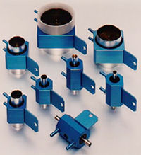
The velocity of the human air current varies considerably according to the rate of respiration. For respiration at rest, the maximum velocities are of the order of 300 to 500 ml./sec; under more strenuous conditions they reach 8000 ml./sec. A single resistance system could not cope with such a wide range of velocities. For this reason eight models are available.
Each model can be used for deliveries exceeding those indicated by 50%; even up to these values there is only a slight discrepancy.
The resistance to respiration offered by the pneumotachograph is very small; it only reaches 15 mm. of water for the largest values measured. This degree of resistance does not affect the respiratory movements and the patient does not notice it.
The rated maximum pressure drop is 10mm. H2O for linear measurement. The differential pressure gauge should be able to discriminate this pressure differential.
Every pneumotachograph is provided with its calibration giving the relationship between the deliveries and the pressure differences between the ducts 5 and 5a. Each apparatus is checked to ensure that it gives equal readings in both directions (inhaling and exhaling). The calibration is independent of the barometric pressure because the differential pressure measured by the pneumotachograph is proportional to the product of delivery and air viscosity, the latter being independent of pressure.
| Type | Maximum Flow | Advisable Flow | Inside Diamter | Length | Dead Space | Weight |
| 00000 | 12 ml/s | 9 ml/s | 1.35 mm | 75 mm | 0.1 ml | 100 g |
| 0000 | 20 | 15 | 6 | 75 | 0.8 | 90 |
| 000 | 60 | 40 | 6 | 75 | 0.9 | 90 |
| 00 | 150 | 100 | 9 | 75 | 2 | 100 |
| 0 | 350 | 250 | 10 | 60 | 4 | 60 |
| 1 | 1.2 l/s | 1 l/s | 18 | 60 | 14 | 100 |
| 2 | 3 | 2.5 | 28 | 60 | 35 | 150 |
| 3 | 8 | 6.5 | 43 | 60 | 80 | 250 |
| 4 | 14 | 11 | 58 | 70 | 172 | 400 |
| 5 | 25 | 21 | 78 | 100 | 460 | 650 |